Products for Incline planning
Incline planning: 14 reduced to 2
Innovative and economical with the LORO-X roof drainage systems

The importance of the “price per liter” illustrated at the example of the new construction project with a roof area of 1.780 m2
In the case of flat roofs, the planning of the roof drainage systems is especially connected to the planning of the roof incline. That is why the collaboration between architects, planners and processors with the producer of the roof drainage systems should begin early enough. Together with the technical service team of the producer, the efficiency can be significantly increased due to the installation of high-quality and powerful complete systems.
Since the start of the new construction project “Katholische Theresienschule in Berlin-Weißensee”, sustainability, longevity and efficiency in all areas were emphasized. That is why also the optimization opportunities for the roof drainage should be discussed with the LORO field service at an early stage.
The price per liter or rather the price per square meter of the roof area that should be drained could be improved by an innovative replanning. During the first meeting it already became clear that the more powerful LORO-X complete systems made of galvanized steel should be used in order to reduce the costs and to be able to use the interior of the building more efficiently.
Incline plan


By planning the low points on flat roofs, the roof area is divided into several part areas. For each of these areas the calculation of the drainage has to be considered separately.
Single low points or so-called low point lines can be planned. Along these lines several main and emergency drains are evenly spread.
For each low point and each low point line at least one main drainage and one emergency drainage has to be installed.
Optimization
Ideally, LORO is already involved in the planning process of the low points on the roof. That way, an optimal drainage concept for the building can be developed from the beginning on. On the basis of your drawings, our service team is also glad to provide support regarding the building-related hydraulic balancing for siphonic flow systems with several drains at one collector pipe without incline.
Then, together an optimum for the size and position of the part areas is found. Thus, the number of drainage points can be minimized and the route of the pipe system can already be determined.

Assessment
Initially, the roof area was divided into two part-areas. For each of these areas a separate low point line was planned. Along these two lines, 5 main drains and 9 emergency drains should be installed that were partly connected to a horizontal collector pipe in the building. This option, however, would have meant a great amount of work, respective tapping holes through the roof, sealings and long pipelines in the interior of the building.

Replanning
Together with the responsible planner the following objectives were set: to reduce the number of drains and roof penetrations, to simplify the installation of the pipes and to move the pipes – if possible – from the inside of the building to the outside. There should be as few roof penetrations as possible and the roof incline should be as simple as possible. The major challenge was to combine the two part-areas and to find one common low point line for the whole roof in order to reduce the number of the required draining points. Here, the collaboration with the producer of the gradient insulation is necessary.
The planning steps
Calculation of the required discharge rate

The calculation of the required discharge rate for the whole roof takes place, for example, with the online calculation on www.loro-x.com.
The result of the calculation was that for a roof area of 1.780 m2with a local rain intensity of 371/668 l/s/ha a discharge rate of at least 66 liter per second for the main drainage and a discharge rate of at least 53 liter per second for the emergency drainage is needed according to the DIN standard.


Basic information on the roof structure
With the aid of the basic information on the roof structure suitable roof drains are selected. This selection can take place via the online configurator on www.loro-x.com, for instance.
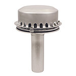
The selection of the suitable system quickly produced an astonishing result: For the complete area of 1.780 m2, 1 LORO-X DRAINJET siphonic drain system for the main drainage as well as 1 system for the emergency drainage with 1 roof drain each is sufficient. The most important change, thus, constituted the replanning of the roof incline so that the rainwater can be securely transported from the roof area to the high-performance drainage systems.
The fact that the proposed emergency drainage system LX961 realizes a discharge rate of up to 94.4 l/s at a water height of 75 mm on the roof, provides increased security in the case of unexpected heavy rain in comparison to the normative calculation on the basis of the average century rainfall.
With aid of the LX specification sheet, system shape and system power of the proposed solution could directly be matched with the construction conditions of the project.
At one glance, the features of the roof drainage system can be found in the practical feature list of the LX specification sheet. With the concise feature list, on the LX specification sheet, complemented by the discharge curve and the system CAD drawing, the planner does not only receive an optimal proof of performance, but simultaneously also a clear illustration of the roof drainage for the processors on the construction site.


Installation
With the new planning of the roof incline as one single U-shaped low point line, several wishes were satisfied at the same time:
The amount of work could be reduced significantly. Instead of 14 only 2 LORO-X drains have to be installed in the roof area. The drains are each positioned directly above the downpipe so that there is no need for a horizontal collector pipe in the building. The initial position of the downpipe connection to the rainwater collecting container in the ground could be maintained. The weather-resistant, break-proof, backflow-proof and optically attractive downpipe made of galvanized steel is installed at the outside of the front building and thus not in the building anymore.
The complete installation of both roof drainage systems took place outside via the open, roofed corridor. That way, the downpipe made of weather-resistant and break-proof LORO-X steel discharge pipe could be installed without any problem. In order to optimally provide the LORO-X DRAINJET roof drains, with the convenient clamping flange as loose and fixed flange construction, with water, the low point line has been widened at the drainage points to secure a circumferential inflow. Due to the newly planned low point line, the required “height” of the gradient insulation could be significantly reduced because the distances between low and high points could be reduced.
Conclusion

Due to the optimal collaboration of the planner and the LORO-X service team, the effort of the roof drainage could at large be significantly reduced. Here, the “price per liter” for the whole drainage solution is determining. LORO’s high performance systems created completely new opportunities for the planning of the roof incline so that the position of the drains and the pipe installation for the rectangular roof area could be simplified. Due to the fact that no penetration from the roof into the fire protection area inside the building is necessary, potential thermal bridges can be excluded and no special fire protection measures have to be taken.
The high-quality complete systems made of galvanized steel offer long-term security and additionally contribute to the sustainability of the building.
DIN Standards
Zero-incline low point lines and the 20m-distance-rule
- DIN 1986-100 chapter 14.2.5 Due to the possible formation of “water hills” when installing zero-incline low point lines it is recommended not to exceed a distance of 20 m between the main drains as well as a distance of 10 m between the main drain and the related emergency drain.
- DIN 1986-100 chapter 14.2.6 In the case of bigger distances, twice the required pressure height shall be determined as roof load at the high point between the distances.
Note: The above-mentioned distance can often be exceeded in favor of more powerful drainage systems if the static concerning the planned low point lines is adjusted respectively. Often fewer drains than usual are required then.
LORO News